In the early 1980s while working at Bell Labs, I was tasked with testing our modems for Electromagnetic Compatibility (EMC) compliance. The work was performed in the EMC test building, which was located on the campus, but required a car ride. All Equipment to be tested and used for testing was required to be brought along. Two pieces of equipment required were a digital modem constellation display converter and a small Constellation Display oscilloscope.
A constellation diagram is a diagram that shows how the information in a digital modulation scheme is represented on a modulated carrier. The display shows when the modem has completed training and is stable and ready to be measured for EMC compliance. Below are some constellations that would be seen after the modem had trained.
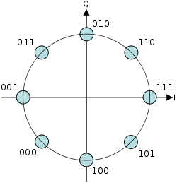 |
8PSK Constellation
|
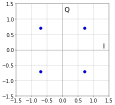 |
QPSK Constellation
|
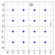 |
| 16 QAM Constellation |
There were many pieces of equipment required to be brought along and I had previously seen a schematic for a 100 LED oscilloscope in a Radio Shack hobby book. I figured I could leave the oscilloscope behind if I could get the LED oscilloscope to work with the constellation generator circuit.
After some initial prototyping, a schematic was provided to the union technician who did a beautiful job. The display granularity was not great, but was adequate for determining when training was complete.
 |
| Rainbow cable connected to modem test connector. |
The banana plugs on the Constellation Converter are for the X, Y and ground when connecting to a oscilloscope.
|
Official Constellation Converter PCB |

 |
| LED Oscilloscope Display Circuit |


No comments:
Post a Comment